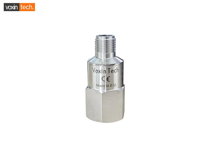


An industrial vibration sensor looks like a simple stainless steel cylinder, but what happens inside it – and how you wire it, scale it and set its alarms – decides whether it protects your machine or just causes nuisance trips. This guide explains the vibration sensor working principle step by step, then covers wiring to a PLC, ISO 10816 limits, trip-point setting and how to stop false trips.

Vibration Sensor Working Principle
Most industrial vibration sensors are built around a piezoelectric element – a small ceramic crystal clamped to a seismic mass inside the housing. When the machine vibrates, the mass pushes and pulls on the crystal, and the crystal produces an electrical charge that is proportional to the acceleration. That raw signal is then processed inside the sensor:
- Charge amplifier – converts the tiny charge from the crystal into a usable voltage.
- Filtering – removes frequencies outside the measuring band (for example 3 Hz to 1000 Hz on Voxintech VT series sensors).
- Integration – converts acceleration into vibration velocity in mm/s, the unit used for machine-health assessment.
- RMS detection – turns the alternating vibration signal into a steady overall value.
- 4–20 mA output stage – sends that value to the PLC as a standard current signal.
Because every step of the vibration sensor working principle happens inside the sensor, the PLC receives a clean, ready-to-use number. You can read more about the piezoelectric effect behind it.
mm/s vs g: Velocity vs Acceleration Measurement
The same vibration can be expressed in three ways – displacement (µm), velocity (mm/s) and acceleration (g). Which one you use depends on the frequency of the problem you want to catch:
| Measurement | Unit | Best for | Typical use |
|---|---|---|---|
| Displacement | µm | Low frequencies | Shaft movement on large sleeve-bearing machines |
| Velocity | mm/s RMS | About 10–1000 Hz | Overall machine health: unbalance, misalignment, looseness |
| Acceleration | g | High frequencies | Early bearing defects and gear mesh problems |
For permanent monitoring and alarms on motors, pumps, fans and gearboxes, a velocity sensor in mm/s is usually the right choice, because it matches the severity limits in ISO standards and gives a stable reading. An acceleration sensor is the better choice when you want early warning of rolling-bearing damage on high-speed machines, usually with an analyser.
ISO 10816 Vibration Limits
ISO 10816-3 (now being replaced by ISO 20816-3) gives vibration severity zones for industrial machines above 15 kW, measured as velocity in mm/s RMS on the bearing housings:
| Machine group and foundation | A/B boundary | B/C boundary | C/D boundary |
|---|---|---|---|
| Group 2 (15–300 kW), rigid foundation | 1.4 | 2.8 | 4.5 |
| Group 2 (15–300 kW), flexible foundation | 2.3 | 4.5 | 7.1 |
| Group 1 (300 kW–50 MW), rigid foundation | 2.3 | 4.5 | 7.1 |
| Group 1 (300 kW–50 MW), flexible foundation | 3.5 | 7.1 | 11.0 |
Zone A is a newly commissioned machine, zone B is acceptable for long-term running, zone C is acceptable only for a limited time, and zone D is severe enough to cause damage. Many plants use the B/C boundary as the warning level and the C/D boundary as the trip level – but always check the machine manufacturer’s recommendation first.
Vibration Sensor Wiring to PLC
2-wire vs 3-wire vibration sensor
A 2-wire (loop-powered) vibration sensor takes its power from the 4–20 mA loop itself, so only two wires run to the PLC. A 3-wire or 4-wire sensor has a separate supply (for example 10–30 V DC), a common 0 V and a 4–20 mA signal wire; the fourth wire can carry a second signal such as temperature. Voxintech VT series sensors use a separate 10–30 V DC supply and an M12 4-pin connector.
Wiring a 3/4-wire sensor to a PLC analog input
- Connect sensor +V to the 24 V DC supply.
- Connect sensor 0 V to the supply 0 V and to the analog input common.
- Connect the 4–20 mA output to the analog input channel, set to “current” mode.
- Use shielded cable and earth the shield at the panel end only.
- Always confirm pin numbers from the sensor datasheet before connecting.
Scaling the signal
Vibration = (measured current − 4 mA) ÷ 16 mA × full-scale range. For example, on a sensor scaled 0–25 mm/s, a reading of 12 mA means (12 − 4) ÷ 16 × 25 = 12.5 mm/s. A reading below about 3.6 mA usually means a broken wire or a failed sensor – set a separate “sensor fault” alarm for it.
How to Set a Vibration Switch Trip Point
Whether you use a mechanical vibration switch or a 4–20 mA sensor with alarms in the PLC or a process indicator, the trip point should come from the machine itself:
- Record a baseline. Log the vibration at normal load for several days, including start-ups.
- Set the warning (alert) level at about 2 times the baseline, or at the ISO B/C boundary, whichever is lower.
- Set the trip (danger) level at about 4 times the baseline, or at the ISO C/D boundary.
- Add a time delay of a few seconds so short spikes do not stop the machine.
- Add a start-up bypass if the machine passes through a resonance while running up to speed.
- Review after one month and adjust if the levels are too close to normal running.
False Trip Vibration Switch Problems – Causes and Fixes
- Trip point too close to normal level – raise it based on the recorded baseline.
- No time delay – impacts, a passing forklift or a valve slam can trip the machine; add 3–10 seconds of delay.
- Start-up and coast-down transients – use a start-up bypass timer.
- Loose or poor mounting – a magnet, thin bracket or loose stud amplifies vibration; stud-mount directly on the bearing housing.
- Electrical noise – route the cable away from VFD and motor power cables and earth the shield at one end only.
- Structural resonance – if the reading changes sharply with small speed changes, move the sensor to a stiffer location.
Vibration Sensor Sensitivity Adjustment
Mechanical vibration switches have a sensitivity knob that changes the force needed to trip. A 4–20 mA vibration transmitter works differently: its measuring range is fixed at the factory, and you “adjust sensitivity” by changing the alarm set-points and time delays in the PLC or indicator. If your machine’s normal level uses only a small part of the range, choose a sensor with a lower full-scale range for better resolution.
Vibration Sensor Calibration
Industrial vibration sensors are calibrated by the manufacturer and normally need no adjustment on site. Good practice is to verify them every one to two years, or whenever readings look suspicious, using a portable vibration calibrator (a small shaker that applies a known vibration, commonly at 159.2 Hz). Compare the 4–20 mA output with the expected value; if it is outside tolerance, replace the sensor rather than trying to adjust it.
Frequently Asked Questions
What is the vibration sensor working principle in simple words?
A small mass inside the sensor presses on a piezoelectric crystal as the machine shakes. The crystal turns that movement into an electrical signal, and the built-in electronics convert it into a 4–20 mA value your PLC can read. Understanding this vibration sensor working principle also explains why stud mounting matters – any looseness changes what the mass feels.
Does a vibration sensor measure velocity or acceleration?
The sensing element measures acceleration. Velocity sensors integrate that signal internally and output mm/s, which is easier to compare with ISO limits.
What is a normal vibration level for a motor?
For a 15–300 kW motor on a rigid foundation, below about 2.8 mm/s RMS is generally acceptable for continuous running under ISO 10816-3. Trend your own machine for the best reference.
Why is my 4–20 mA vibration reading stuck at 4 mA?
Check the supply voltage, the wiring polarity and the PLC input mode. A steady 4 mA can also simply mean the machine is stopped or running very smoothly.
Looking for prices and model selection? Read our vibration sensor price in India buying guide or see the full range of industrial vibration sensors. For help with wiring or set-points, call or WhatsApp +91 99530 39482 or request a quote.